Nov. 21, 2025
Remarks:
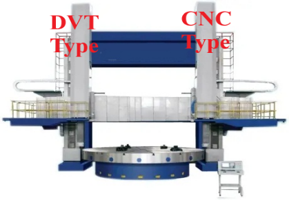
Left Tool Post is DVT Type, Right Tool Post is CNC Type (Siemens 808D, 828D, FANUC etc.).
If customer need 2 tool post same CNC type, we can do as per customer’s requirement at extra cost.
| No. | Specification | Value |
|---|---|---|
| 1 | Maximum processing diameter | 4000 mm |
| 2 | Workbench diameter | 3200 mm |
| 3 | Maximum processing height | 2000 mm |
| 4 | Maximum workpiece weight | 20 T |
| 5 | Workbench maximum torque | 80 kN·m |
| 6 | Worktable speed steps | 4 steps (continuously variable within each step) |
| 7 | Workbench speed range | 1–50 r/min |
| 8 | Vertical knife holder horizontal stroke | –50 to 2150 mm |
| 9 | Vertical tool holder slider stroke | 1200 mm |
| 10 | Slide pillow cross-sectional size | 240 × 240 mm |
| 11 | Right tool holder cutting force | 40 kN |
| 12 | Left tool holder cutting force | 35 kN |
| 13 | Knife holder feed range | 0.1–500 mm/min |
| 14 | Feed rate series | Stepless |
| 15 | Knife holder rapid movement speed | 2000 mm/min |
| 16 | Feed servo motor torque | 30 N·m |
| 17 | Main motor power | 55 kW |
| 18 | Beam lifting motor power | 11 kW |
| 19 | Machine weight (approx.) | 50 T |
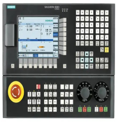
1) CNC system Siemens 808D, control the RIGHT TOOL POST 2 axis (X, Z)
2) The LEFT TOOL POST is with ball screw transmission, DVT type.
3) Interpolate straight lines and arcs
4) Compensate for backlash, pitch error, tool wear and tool nose radius compensation
5) The coordinate setting is set according to the workpiece coordinate
6) Monitor color English display
7) Controller built-in programmable controller
8) Programming directly according to the drawing size data
9) Feedrate override multi-segment override rapid operation
10) Feed automatic feed and manual electronic handwheel control
11) Alarm display of the alarm control part
12) Interfaces External computer interface, RS-232C, CF card
13) Real-time profiling graphics real-time display
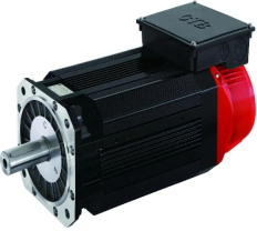
1) Main motor AC SERVO 55KW, Beijing CTB brand, China famous brand
2) Automatic Lubrication Station, Guangdong Foshan, China famous brand
3) Lead screw Taiwan ABBA, imported
4) CNC system SIMENS 808D
5) Servo driver SIEMENS
6) Main electric parts SCHNEIDER, France
7) Main bearing, China Top1 brand ZWZ (www.zwz-bearing.com )
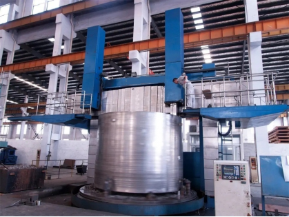
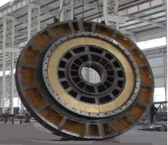
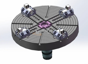
The machine is a gantry type structure. There are left and right columns, connecting beams and the base of the worktable. Interconnected to form a frame structure, consisting of gantry, main transmission gearbox, worktable, beam, horizontal beam lifting mechanism, left and right vertical tool rest, hydraulic device, electric control cabinet, etc.
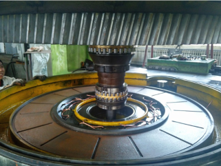
A double row radial cylindrical roller bearing is installed on the main shaft of the worktable, and its inner ring has a tapered hole.
The entire radial clearance is ensured to ensure the accuracy of the spindle. The worktable adopts constant flow static pressure guide rail, and each oil cavity is made of high-precision, The multi-head pump injects equal amount of required pressure oil into each oil cavity to bear the vertical load. on the spindle the upper part is equipped with a self-aligning roller bearing with oil film preload, so that the hydrostatic guideway has high oil film rigidity and small end face runout. The center of the table is equipped with an unloading bearing with a large load capacity, when the workpiece is heavy, At the same time, the central unloading bearing and the static pressure guide rail support the workpiece rotation at the same time, reduce the deformation of the worktable, make the The hydrostatic guides are in good condition.
In order to reduce the influence of the thermal deformation of the worktable on the machining accuracy, a thermally symmetrical structure is adopted to achieve the small thermal deformation of the workbench, the thermal deformation in the same left and right directions ensures the long-term stability of the workbench.
Work.
The table is equipped with a spindle encoder for constant speed cutting and threading The gearbox is driven by an AC55KW motor, and the shifting of the gearbox is driven by hydraulic cylinders. The gear is made of 42 chrome-molybdenum, and the hardness is up to HRC52-58, the accuracy can reach 6 grades.
The gantry is composed of left and right columns and connecting beams. There is a lift box on the upper part of the gantry,Driven by the flow motor, the beam moves up and down along the left and right column guide rails through the worm gear pair and the double lead screw.
The left and right columns of the machine tool, connecting beams and other large parts are made of high-strength, low-stress cast iron materials, with high hardness
HB170-190, make the machine tool have greater strength and higher rigidity, after aging treatment, eliminate
The Stress determines the accuracy of the machine.
It is composed of beam, horizontal feed transmission structure, clamping mechanism and hydraulic device.
The beam is made of high-strength and low-stress cast iron, with sufficient rigidity and strength, after aging treatment, Ensure the accuracy of the machine. The junction surface of the beam and the column guide is adhered with PTFE wear-resistant guide soft tape, which has The small friction number greatly prolongs the service life of the machine tool. The beam is placed in front of the column so that the beam moves vertically on the column. There are 4 hydraulic clamping points behind the beam, the clamping mechanism is connected to the beam,The lift motor and lubrication are interlocked and controlled by the beam lifting button to ensure the stability of the beam.
The left turret is controlled by DVT system, and the right turret is controlled by Siemens 808D numerical control system, which consists of beam sliding seat, ram, balance oil cylinder, ball screw and planetary reducer. The tool holder is driven by a servo motor and a driver. The tool holder can move horizontally on the beam, the ram moves vertically along the sliding seat, the planetary reducer reduces the speed to increase the torque, and the ball screw drives the tool holder to work. The tool holder ram is equipped with a hydraulic balance device to balance part of the weight of the ram and make the ram move smoothly.
The main control components of the hydraulic system are all made by famous manufacturers at home and abroad with reliable performance. The main functions of the system are:
①Provide shifting power for the hydraulic cylinder of the main transmission gearbox;
② Supply oil for the static pressure device of the guide rail of the worktable;
③ Supply oil for the ram balance cylinder;
④ Supply oil for the beam clamping cylinder system;
⑤ Lubrication and oil supply related to machine tools.
Each lubrication system of the whole machine is equipped with automatic lubrication to ensure that each lubrication point can be fully lubricated regularly and quantitatively.
Machine electric system control components and motor drive units are installed in independent power distribution cabinets, and all operating components are centrally installed on the floor-standing cabinet button station. The operation control part is concentrated on an independent button station, and the CNC tool holder is equipped with a hand-held unit, which is simple, convenient and flexible to operate.
Power supply: three-phase AC 380V±10%, 50HZ.
The electrical design of the machine tool complies with the international general design standards and can meet the buyer's relevant technological requirements, with necessary interlocking, interlocking and protection devices.
|
Item1
The non-perpendicularity of the column guide to the base guide: a) In a plane parallel to the positive rail of the column. b) In a plane perpendicular to the positive rail of the column.
a: 0.03mm/1000mm
b: 0.03mm/1000mm |
|
Item2
The unevenness of the work surface On table diameter: Max. 0.04mm/1000mm On table full length of diameter: Max. 0.06mm The worktable can only be concave |
|
Item 3
End runout of work surface Max. 0.03mm |
|
Item 4
Radial runout of the table Max. 0.03mm
|
|
Item 5
Tilt clearance when the beam moves
On beam per 1 meter travel: Max. 0.04mm Over the full travel of the beam: Max. 0.05mm |
|
Item6 a) Non-parallelism of the horizontal movement of the vertical tool holder to the work surface
Max. 0.05mm / 1000mm horizontal stravel Only the middle of the beam is allowed to deviate from the table.
b) The unstraightness of the horizontal movement of the vertical tool rest Max. 0.04 on the table radius. |
|
Item7
a) The non-perpendicularity of the movement of the vertical tool rest ram to the work surface Max. 0.03mm / 500mm stroke
b) Unstraightness of the movement of the ram of the vertical knife rest over the full stroke: Max. 0.05mm |
| Specification | Value |
|---|---|
| Roundness of the workpiece | Max. 0.03 mm |
| Consistency of machining diameter | Max. 0.02 mm (on 300 mm measuring length) |
| Workpiece flatness | Max. 0.03 mm / Ø1000 mm |
| Surface roughness of the workpiece | Max. Ra 1.6 μm |
| Positioning accuracy (X-axis) | 0.025 mm / 1000 mm |
| Positioning accuracy (Z-axis) | 0.025 mm / 1000 mm |
| Repeatability (X-axis) | 0.015 mm |
| Repeatability (Z-axis) | 0.015 mm |
Navigation
Categories
Get in Touch
Service Hotline
+86 029-82697808
Address
Ruisen-Yunfeng Building, No.29 Nanerhuan East Road, Xi'An 710054 Shaanxi Province, China.